 KR Webzine Vol.132
- Dec. 2021
- Nov. 2021
- Oct. 2021
- Sep. 2021
- Aug. 2021
- Jul. 2021
- Jun. 2021
- May. 2021
- Apr. 2021
- Mar. 2021
- Feb. 2021
- Jan. 2021
- Dec. 2020
- Nov. 2020
- Oct. 2020
- Sep. 2020
- Aug. 2020
- Jul. 2020
- Jun. 2020
- May. 2020
- Apr. 2020
- Mar. 2020
- Feb. 2020
- Jan. 2020
- Dec. 2019
- Nov. 2019
- Oct. 2019
- Sep. 2019
- Aug. 2019
- Jul. 2019
- Jun. 2019
- May. 2019
- Apr. 2019
- Mar. 2019
- Feb. 2019
- Jan. 2019
- Dec. 2018
- Nov. 2018
- Oct. 2018
- Sep. 2018
- Aug. 2018
- Jul. 2018
- Jun. 2018
- May. 2018
- Apr. 2018
- Mar. 2018
- Feb. 2018
- Jan. 2018
- Dec. 2017
- Nov. 2017
- Oct. 2017
- Sep. 2017
- Aug. 2017
- Jul. 2017
- Jun. 2017
- May. 2017
- Apr. 2017
- Mar. 2017
- Feb. 2017
- Jan. 2017
- Dec. 2016
- Nov. 2016
- Oct. 2016
- Sep. 2016
- Aug. 2016
- Jul. 2016
- Jun. 2016
- May. 2016
- Apr. 2016
- Mar. 2016
- Feb. 2016
- Jan. 2016
- Dec. 2015
- Nov. 2015
- Oct. 2015
- Sep. 2015
- Aug. 2015
- Jul. 2015
- Jun. 2015
- May. 2015
- Apr. 2015
- Mar. 2015
- Feb. 2015
- Jan. 2015
- Dec. 2014
- Nov. 2014
- Oct. 2014
- Sep. 2014
- Aug. 2014
- Jul. 2014
- Jun. 2014
- May. 2014
- Apr. 2014
- Mar. 2014
- Feb. 2014
- Jan. 2014
- Dec. 2013
- Nov. 2013
- Oct. 2013
- Sep. 2013
- Aug. 2013
- Jul. 2013
- Jun. 2013
- May. 2013
- Apr. 2013
- Mar. 2013
- Jan. 2013
- Dec. 2012
- Nov. 2012
- Oct. 2012
- Sep. 2012
- Aug. 2012
- Jul. 2012
- Jun. 2012
- May. 2012
- Apr. 2012
- Mar. 2012
- Feb. 2012
- Jan. 2012
- Dec. 2011
- Nov. 2011
- Oct. 2011
- Sep. 2011
- Aug. 2011
- Jul. 2011
- Jun. 2011
- May. 2011
- Apr. 2011
- Mar. 2011
- Feb. 2011
- Jan. 2011
- Dec. 2010
- Nov. 2010
- Oct. 2010
- Sep. 2010
- Aug. 2010
- Jul. 2010
- Jun. 2010
- May. 2010
- Apr. 2010
- Mar. 2010
- Feb. 2010
- Jan. 2010
- Dec. 2009
- Nov. 2009
- Oct. 2009
- Sep. 2009
- Aug. 2009
- Jul. 2009
- Jun. 2009
- May. 2009
- Apr. 2009
- Mar. 2009
- Feb. 2009
- Jan. 2009
- Dec. 2008
- Nov. 2008
- Oct. 2008
- Sep. 2008
- Aug. 2008
- Jul. 2008
- Jun. 2008
- May. 2008
- Apr. 2008
- Mar. 2008
- Feb. 2008
02
February 2019
1. Introduction
In general, the combination of load directions used in mooring analysis of floating offshore structures reflects the characteristics of the Metocean data in the sea area, and if this is impossible, it is performed by finding the worst case according to various combinations of load directions (BV, 2015).
In cases where there is no directional data, it is recommended to define the combination of load direction as two cases of Collinear and Non-Collinear for the analysis of turret mooring system (DNVGL 2015). However, there is a possibility of discrepancy because the standard and criterion are not the same. In this study, a parametric study on the combination of load directions is performed to find the compromised coverage of each load direction applied in the analysis of a turret mooring system.
2. Mooring system analysis
The analysis of a mooring system is generally performed according to the procedure shown in Figure 1.
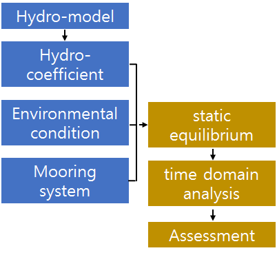
Figure 1. General procedure of mooring analysis
2.1 Target model
The target model is a FPSO developed by Samsung Heavy Industries, and details are shown in Table 1.
Table 1. Details of FPSO
|
Item |
Unit |
Max. Storage |
|
LPP |
m |
244 |
|
B |
m |
50 |
|
TF |
m |
18.6 |
|
TA |
m |
18.6 |
|
V |
m³ |
163,215 |
|
GM |
m |
4.43 |
|
XCG |
m |
117.7 |
|
YCG |
m |
0 |
|
VCG |
m |
18.5 |
|
kxx |
m |
15.2 |
|
kyy |
m |
59.3 |
|
kzz |
m |
60.0 |

Figure 2. Analysis model
The analysis model is shown in Figure 2 and consists of 2,000 panels and nodes.
2.2 Coordinate system
The program used for mooring analysis is ANSYS AQWA, and the coordinate system applied to the program is shown in Figure 3. Head Sea is defined as ±180°.
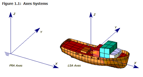
Figure 3. Coordinate convention
2.3 Turret mooring system
In the turret mooring system, four groups of four lines are applied as shown in Figure 4, and each mooring line consists of three kinds of top chain, steel wire and bottom chain. Details of the mooring line are shown in Table 2.
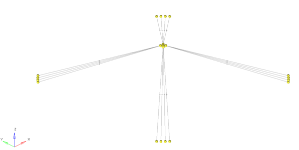
Figure 4. Mooring system
Table 2. Details for mooring line
|
Item |
Unit |
Top chain |
Steel wire |
Bottom chain |
|
Length |
m |
80m |
100m |
300m |
|
Diameter |
mm |
171mm |
153mm |
171mm |
|
Unit Weight in Water |
kN/m |
4.96 (505.6kg/m) |
1.01(103.0kg/m) |
4.96(505.6kg/m) |
|
Unit weight in air |
Kg/m |
505.6+(1025*0.046) |
103.0+(1025*0.018) |
|
|
Elastic Modulus(AE) |
kN |
2.49E+06 |
2.11E+06 |
2.49E+06 |
|
MBL |
kN |
26,952 |
21,068 |
26,952 |
3. Parametric Study
3.1 First study: directional combination between 180° and 0°
In order to find the tendency of the results according to the combination of load directions, the direction of the wave load is fixed at 180°, and the incidence angles of current and wind loads are set at intervals of 30° between 180° and 0° for the mooring analysis as shown in Figure 5.
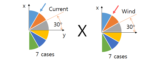
Figure 5. Cases for directional combinations (180~0°)
3.2 The results for the first study
After the analysis of Section 3.1, the load combinations corresponding to the upper 10% (5 combinations) of the maximum offsets among the 49 cases of the floating offshore structure are selected. As a result, it is found that the load combinations are concentrated at 180~90°. The top 10% of directional combinations are shown in Table 3.
Table 3. Top 10% of directional combinations
|
Wave |
Wind |
Current |
|
180 |
180 |
150 |
|
180 |
180 |
180 |
|
180 |
150 |
120 |
|
180 |
150 |
90 |
|
180 |
150 |
180 |
3.3 Second study: directional combination between 180° and 90°
Based on the results of Section 3.2, it is found that the maximum offset corresponding to the upper 10% is concentrated in the range of 180~90°. Based on this, the interval of angle for the combination of directions is divided into 15° within the range of 180~90° to analyze the characteristics of combinations as shown in Figure 6.
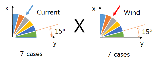
Figure 6. Cases for directional combinations (180~90°)
According to the Section 3.3, the direction of the wave is fixed at 180° and the direction of the current and the wind are changed from 180° to 90° at intervals of 15°. 49 cases are analyzed and offset results are obtained for each condition.
Based on this, a trend analysis on load directions is performed. The results are shown in Figure 7 and Figure 8.
As shown in Figure 7, the direction of seven winds is changed in seven current directions and the offsets are found to have the maximum value between 135° and 90°.
When the reference load is set to wind in the same analysis method, the maximum value is found between 180° and 120° as shown in Figure 8.
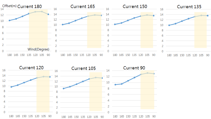
Figure 7. Offset result by wind direction with respect to current
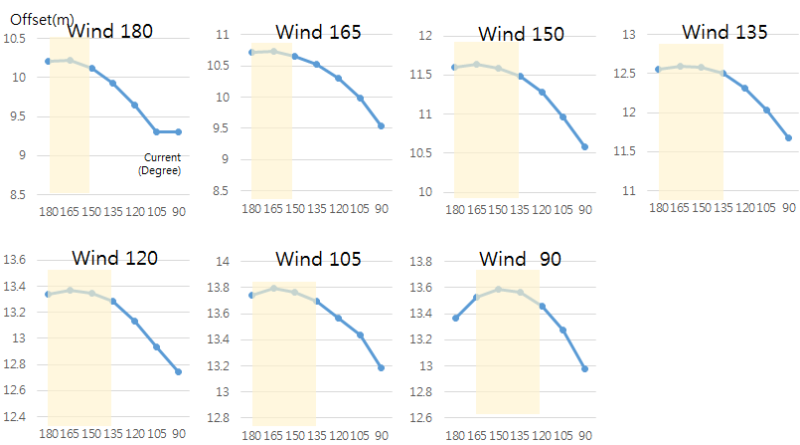
Figure 8. Offset result by current direction with respect to wind direction
4. Sensitivity analysis of loads
The turret mooring system can induce a reduction of the load by changing the heading angle according to the direction of the dominant load.
The change of heading angle caused by weather vaning is confirmed from the analysis results of 49 cases with wind and current load combinations that are set at intervals of 15° in the range of 80° to 90°.
The effect of weather vaning is confirmed under two conditions of fixing wind direction at 180° and fixing current direction at 180°. The results are shown in Figure 9.
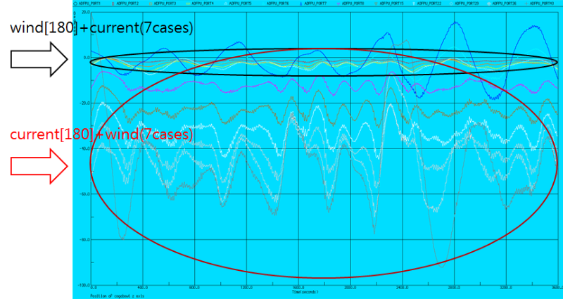
Figure 9. Comparison of trends of heading angle with respect to wind and current directions
When the wind direction is fixed, it is found that the change of the heading angle is about 10° from 180° to 170° where the direction of the current changes from 180° to 90°. On the contrary, when the direction of the current is fixed, the change of the heading angle caused by the wind is about 90° from 180° to 90°, and it is found that the behavior is similar to the wind direction.
As a result, it is found that the analysis result of this study is dominated by the influence of wind.
5. Conclusion
In order to investigate the influence of the combination of load directions applied to a turret mooring system with respect to offshore structure offsets, the direction combinations of various loads are analyzed and the tendency is verified through the results.
In the case of current, the maximum offsets tend to occur between 180° and 135°, and the winds tend to have maximum offsets between 135° and 90°.
As a result of the sensitivity analysis on the weather vaning according to the load directions, it is found that the direction of wind is dominant, which means that the result of this analysis is influenced by the wind load and its direction.
These results suggest that it is difficult to specify the range of the combination of the load direction narrowly because there are various variables that can change the result. It is recommended to derive the maximum offset through the direction combination between 180° and 90° in the mooring analysis.
As a result, further studies on various parameters such as the influence of each load factor and the change of the form of the mooring system are considered to be needed.


