 KR Webzine Vol.127
- Dec. 2021
- Nov. 2021
- Oct. 2021
- Sep. 2021
- Aug. 2021
- Jul. 2021
- Jun. 2021
- May. 2021
- Apr. 2021
- Mar. 2021
- Feb. 2021
- Jan. 2021
- Dec. 2020
- Nov. 2020
- Oct. 2020
- Sep. 2020
- Aug. 2020
- Jul. 2020
- Jun. 2020
- May. 2020
- Apr. 2020
- Mar. 2020
- Feb. 2020
- Jan. 2020
- Dec. 2019
- Nov. 2019
- Oct. 2019
- Sep. 2019
- Aug. 2019
- Jul. 2019
- Jun. 2019
- May. 2019
- Apr. 2019
- Mar. 2019
- Feb. 2019
- Jan. 2019
- Dec. 2018
- Nov. 2018
- Oct. 2018
- Sep. 2018
- Aug. 2018
- Jul. 2018
- Jun. 2018
- May. 2018
- Apr. 2018
- Mar. 2018
- Feb. 2018
- Jan. 2018
- Dec. 2017
- Nov. 2017
- Oct. 2017
- Sep. 2017
- Aug. 2017
- Jul. 2017
- Jun. 2017
- May. 2017
- Apr. 2017
- Mar. 2017
- Feb. 2017
- Jan. 2017
- Dec. 2016
- Nov. 2016
- Oct. 2016
- Sep. 2016
- Aug. 2016
- Jul. 2016
- Jun. 2016
- May. 2016
- Apr. 2016
- Mar. 2016
- Feb. 2016
- Jan. 2016
- Dec. 2015
- Nov. 2015
- Oct. 2015
- Sep. 2015
- Aug. 2015
- Jul. 2015
- Jun. 2015
- May. 2015
- Apr. 2015
- Mar. 2015
- Feb. 2015
- Jan. 2015
- Dec. 2014
- Nov. 2014
- Oct. 2014
- Sep. 2014
- Aug. 2014
- Jul. 2014
- Jun. 2014
- May. 2014
- Apr. 2014
- Mar. 2014
- Feb. 2014
- Jan. 2014
- Dec. 2013
- Nov. 2013
- Oct. 2013
- Sep. 2013
- Aug. 2013
- Jul. 2013
- Jun. 2013
- May. 2013
- Apr. 2013
- Mar. 2013
- Jan. 2013
- Dec. 2012
- Nov. 2012
- Oct. 2012
- Sep. 2012
- Aug. 2012
- Jul. 2012
- Jun. 2012
- May. 2012
- Apr. 2012
- Mar. 2012
- Feb. 2012
- Jan. 2012
- Dec. 2011
- Nov. 2011
- Oct. 2011
- Sep. 2011
- Aug. 2011
- Jul. 2011
- Jun. 2011
- May. 2011
- Apr. 2011
- Mar. 2011
- Feb. 2011
- Jan. 2011
- Dec. 2010
- Nov. 2010
- Oct. 2010
- Sep. 2010
- Aug. 2010
- Jul. 2010
- Jun. 2010
- May. 2010
- Apr. 2010
- Mar. 2010
- Feb. 2010
- Jan. 2010
- Dec. 2009
- Nov. 2009
- Oct. 2009
- Sep. 2009
- Aug. 2009
- Jul. 2009
- Jun. 2009
- May. 2009
- Apr. 2009
- Mar. 2009
- Feb. 2009
- Jan. 2009
- Dec. 2008
- Nov. 2008
- Oct. 2008
- Sep. 2008
- Aug. 2008
- Jul. 2008
- Jun. 2008
- May. 2008
- Apr. 2008
- Mar. 2008
- Feb. 2008
09
September 2018
According to IMO classification, liquefied gas carriers are either categorized as independent self-supporting tanks or non-self-supporting tanks. Self-supporting tanks are further classified into Type A, Type B and Type C. Non-self-supporting tanks are also known as membrane type tanks and today the most popular membrane type patents are owned by Gaz Transport & Technigaz (GTT). GTT technology is used in two main types of cargo containment system (CCS) used for the membrane-type ships, namely Mark III and No. 96. There are also many new CCS systems are being developed around the world.
Because the steel hull of an LNG carrier may become brittle at the low temperatures caused by the liquefaction of the cargoes, temperature distribution analysis is performed to calculate the accurate temperature of the hull. Based on the expected calculated temperature, the optimum steel grade for the hull is selected. Currently, GTT (Mark III, NO .96), KOGAS (KC-1) and Korean shipyards (SOLIDUS, DCS-16, SCA-WS) are performing temperature distribution analysis for their own CCS systems, but each of their procedures and assumptions differ from each other. Also, no IACS member class society has published guidelines for LNGC temperature calculations. To help address this, KR has developed new guidelines for LNGC temperature distribution analysis. This recognizes the requirement for such rules and guidelines and the need to objectively verify them. The guidelines cover the procedures for temperature calculation of membrane type LNG carriers. More research is ongoing on temperature distribution analysis for independent self-supporting tank liquefied gas carriers. Once that research is completed, KR guidelines will be updated to include temperature distribution analysis procedures for independent self-supporting tanks.
The following two temperature calculation methods have been developed;
- Analytical temperature distribution analysis method
- Finite element temperature distribution analysis method
Type A Tank:
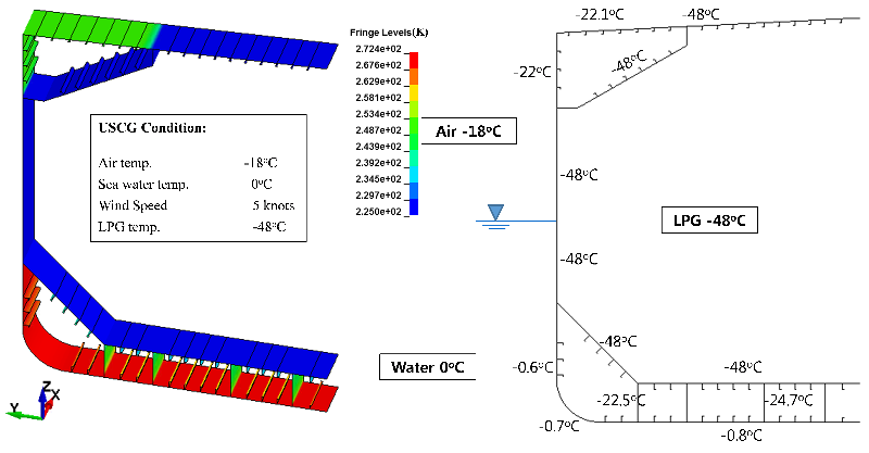
Type A tanks are primarily constructed of flat surfaces and are widely used for LPG carriers. The maximum allowable tank design pressure in the vapor space for this type of system is 0.7 barg; this means cargoes must be carried in a fully refrigerated condition at or near atmospheric pressure. Both IMO and USCG design conditions are considered in the analysis. Temperature calculations are performed considering the static fully loaded condition with the secondary barrier assumed to be at the cargo temperature. Calculations also consider the static fully loaded condition at a heeling angle of 30o with the secondary barrier assumed to be at the cargo temperature.
The temperature calculation is performed by both analytical and FEM methods. 2D FEM is applied to calculate temperature along the transverse section of the hull. 3D FEM is used to calculate temperatures of the forward and aft cofferdam.
Figure 1 illustrates temperature calculation results for a typical Type A tank using 2D FEM.
 Figure 1. Temperature calculation for Type A tank using 2D FEM
Type B Tank:
Type B independent tanks can be constructed of flat surfaces or they may be of the spherical type, the design vapor pressure is less than 0.7 barg. Type B tanks are mostly used on LNG carriers where the tank is externally insulated with foam material. Cargo hold spaces contain dry air or may also be inerted. Type B tanks only require a partial secondary barrier in the form of a drip tray due to enhanced design features.
Analytical, 2D & 3D FEM temperature distribution analysis is performed for the structural member temperature calculations.
Figure 2 presents temperature calculation results performed for a cofferdam of a Type B LNG carrier using 3D FEM.

Figure 2. Temperature distributions in the cofferdam calculated by 3D FEM
In membrane type LNGCs, the cofferdam bulkhead temperature falls below -30 oC in the zero heating condition. However, in case of Type B LNGCs, the cofferdam bulkhead temperature remains higher than -30 oC and therefore grade E or DH steel could be used.
Type C Tank:
Type C independent tanks are normally spherical or cylindrical pressure vessels having design pressures higher than 2 barg. Type C is the dominant design for LNG fueled ships but they are also used in small LNG or LPG carriers and always used for semi-pressurized or fully pressurized gas carriers. Horizontal cylindrical tanks poorly utilize the hull volume and so can be improved by using intersecting pressure vessels or bilobe type tanks.
Analytical, 2D & 3D FEM can be used for the temperature calculation of Type C gas carrier hulls. Currently, KR is conducting more research into Type C tanks in order to investigate if there are any special issues to be considered for temperature distribution analysis.
Temperature Distribution Analysis Software:
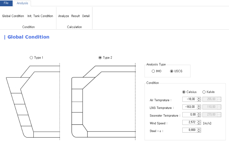
KR has developed membrane type LNGC hull temperature calculation software which is based on the analytical method and can be applied for temperature calculations along the transverse direction of the hull. The verification of the KR software has been undertaken by comparing LNGC hull temperature results calculated by GTT and using KR software. More research is ongoing to update the software and to extend the capabilities for temperature calculations of independent self-supporting tank liquefied gas carriers.

Figure 3. KR software for temperature calculation of LNGC hull
Temperature distribution analysis is an obligatory and important task for design of liquefied gas carriers. Following KR guidelines and using KR software, the user would be able to perform temperature distribution analysis easily and calculate hull temperatures accurately.


