 KR Webzine Vol.126
- Dec. 2021
- Nov. 2021
- Oct. 2021
- Sep. 2021
- Aug. 2021
- Jul. 2021
- Jun. 2021
- May. 2021
- Apr. 2021
- Mar. 2021
- Feb. 2021
- Jan. 2021
- Dec. 2020
- Nov. 2020
- Oct. 2020
- Sep. 2020
- Aug. 2020
- Jul. 2020
- Jun. 2020
- May. 2020
- Apr. 2020
- Mar. 2020
- Feb. 2020
- Jan. 2020
- Dec. 2019
- Nov. 2019
- Oct. 2019
- Sep. 2019
- Aug. 2019
- Jul. 2019
- Jun. 2019
- May. 2019
- Apr. 2019
- Mar. 2019
- Feb. 2019
- Jan. 2019
- Dec. 2018
- Nov. 2018
- Oct. 2018
- Sep. 2018
- Aug. 2018
- Jul. 2018
- Jun. 2018
- May. 2018
- Apr. 2018
- Mar. 2018
- Feb. 2018
- Jan. 2018
- Dec. 2017
- Nov. 2017
- Oct. 2017
- Sep. 2017
- Aug. 2017
- Jul. 2017
- Jun. 2017
- May. 2017
- Apr. 2017
- Mar. 2017
- Feb. 2017
- Jan. 2017
- Dec. 2016
- Nov. 2016
- Oct. 2016
- Sep. 2016
- Aug. 2016
- Jul. 2016
- Jun. 2016
- May. 2016
- Apr. 2016
- Mar. 2016
- Feb. 2016
- Jan. 2016
- Dec. 2015
- Nov. 2015
- Oct. 2015
- Sep. 2015
- Aug. 2015
- Jul. 2015
- Jun. 2015
- May. 2015
- Apr. 2015
- Mar. 2015
- Feb. 2015
- Jan. 2015
- Dec. 2014
- Nov. 2014
- Oct. 2014
- Sep. 2014
- Aug. 2014
- Jul. 2014
- Jun. 2014
- May. 2014
- Apr. 2014
- Mar. 2014
- Feb. 2014
- Jan. 2014
- Dec. 2013
- Nov. 2013
- Oct. 2013
- Sep. 2013
- Aug. 2013
- Jul. 2013
- Jun. 2013
- May. 2013
- Apr. 2013
- Mar. 2013
- Jan. 2013
- Dec. 2012
- Nov. 2012
- Oct. 2012
- Sep. 2012
- Aug. 2012
- Jul. 2012
- Jun. 2012
- May. 2012
- Apr. 2012
- Mar. 2012
- Feb. 2012
- Jan. 2012
- Dec. 2011
- Nov. 2011
- Oct. 2011
- Sep. 2011
- Aug. 2011
- Jul. 2011
- Jun. 2011
- May. 2011
- Apr. 2011
- Mar. 2011
- Feb. 2011
- Jan. 2011
- Dec. 2010
- Nov. 2010
- Oct. 2010
- Sep. 2010
- Aug. 2010
- Jul. 2010
- Jun. 2010
- May. 2010
- Apr. 2010
- Mar. 2010
- Feb. 2010
- Jan. 2010
- Dec. 2009
- Nov. 2009
- Oct. 2009
- Sep. 2009
- Aug. 2009
- Jul. 2009
- Jun. 2009
- May. 2009
- Apr. 2009
- Mar. 2009
- Feb. 2009
- Jan. 2009
- Dec. 2008
- Nov. 2008
- Oct. 2008
- Sep. 2008
- Aug. 2008
- Jul. 2008
- Jun. 2008
- May. 2008
- Apr. 2008
- Mar. 2008
- Feb. 2008
08
August 2018
1. General
The blade of a wind turbine is an important component in the system. Generally, in the design stage various considerations must be taken into account such as the interactions between output and efficiency, blade tip and tower clearance, extreme and fatigue limit states, buckling stability, transportation, manufacturing expenses and cost of energy (COE). Thus, the aerodynamic design and structural design of the blade can’t be conducted independently, and it is important to obtain results for an optimal blade design by repeating the integrated load analysis, incorporating the entire system.
In addition, the target output and efficiency, annual energy production (AEP), axis load and noise are also considered to be important design considerations, by lengthening chord length and applying thin airfoil enhances the aerodynamic design of a blade delivering excellent performance.
However, such a design can cause problems in load, manufacturing costs, total mass, and transportation, it is placed in a conflicting relation (trade-offs) with the structural design.
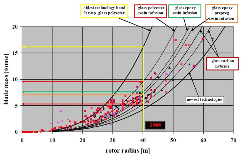
[Blade distribution base on the length, mass, materials]
2. Process of Blade design
Once the design specification is determined, the aerodynamic design analysis selects the candidate group of air foil and conducts basic aerodynamic design and performance research obtaining reliable air foil performance data through tests or numerical analysis.
Basic aerodynamic design is generally conducted by BEM and goes through a design optimization process based on the evaluation results of the output/efficiency/load. If the design conditions are satisfied in the optimal design process, the final aerodynamic design information is sent to the structural design team. In the structural design stage, a design concept is decided after considering material and manufacturing procedures, and the internal structure (main girder, shear web, root connection) and lamination pattern designs are decided upon.
After the structural design of the blade has been decided, the design validity is verified through a structural integrity evaluation based on international standards or industrial guidelines. A record of the extreme and fatigue load which will be applied to the blade route and specific cross sections during its design life time is required. Therefore, after the structural design is completed, a finite element analysis (FEA) is required to obtain the mass and stiffness distribution on the local cross section of the blade, which is necessary to conduct a system integrated load calculation.
The system load stage defines the design load case by referring to the applied criteria and deriving the aero-elastic analysis results for the extreme and fatigue load applied to blade. The structural design stage, includes an FEA to obtain analysis results on the tip-tower gap (critical deflection evaluation), extreme state, fatigue limit state and structural stability. Following this, the blade design is finalized if all the analysis results satisfy the criteria, and a redesign is undertaken if they don't meet the design targets. Therefore, simultaneously conducting wind turbine system and blade design is the most efficient method to develop a suitable blade for a specific wind turbine system.

[Blade after aerodynamic design]
3. Aerodynamic design
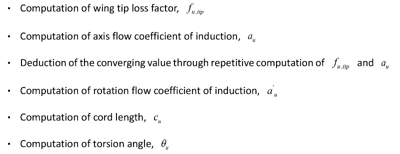
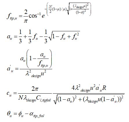
Through aerodynamic design, the blade length, airfoil series placement on the local cross section, the cord length and torsion angle that satisfy the target output and efficiency in a rated wind speed are all determined. The aerodynamic design process begins with basic aerodynamic design and the cord length and torsion angle on a two-dimensional local cross section. This is designed beforehand by the designer from root to tip, and is computed using the design variable values. The cord length and torsion angle can be computed by equations (1) ~ (5) based on the following steps
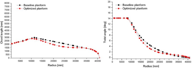
[Chord length distribution] [Twist angle distribution]
4. Structural Design
This paper focuses on a blade designed with a 2MW rated output, IEC wind level IIa and 40.1m length. Unidirectional, biaxial and triaxle glass fibers were used and PVC foam with a high resin affinity was applied. For a smooth structural design, the blade is divided into 11 detailed parts based on the major materials used in the design and their locations.
ㆍ Pressure side spar cap
ㆍ Suction side spar cap
ㆍ First and second shear web
ㆍ Trailing edge
ㆍ Blade root
ㆍ Extra root (in total 11 parts)
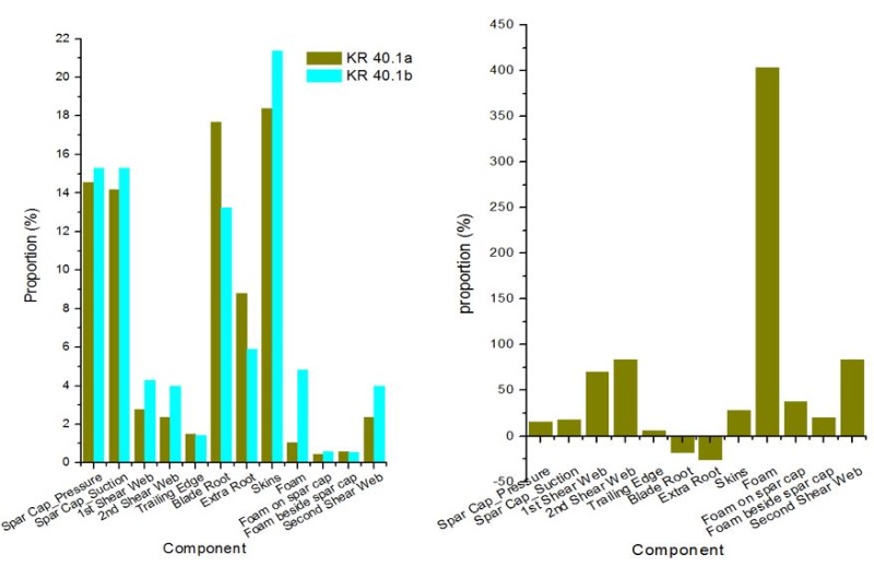
[Comparison of component mass of blade]
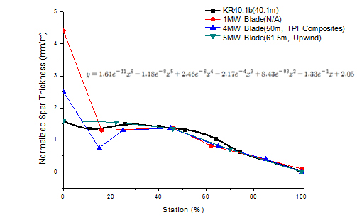
The diagram below shows the normalized spar cap thickness of the blade and those of other blades. A comparison of blade characteristics (stiffness/mass/thickness etc.) is a method that is applied by multiple blade design organizations to verify the design validity at the blade design and review phase, and it is a useful method to confirm the design validity when they do not collect much of their own data. The spar cap thickness data of the three types of blades which are compared for references are blade models that respectively have 1MW, 4MW, 5MW capacities.
Through the comparison, we can check that the spar cap thickness ratio of KR Blade shows a similar trend to the thickness ratios of the three types of reference models. The normalized spar cap thickness of the four models is similar, which means that stiffness of the normalized spar cap is also similar, and the following is the reason why. The stiffness of composite lamination in classical lamination theory is composed of A matrix (extensional stiffness matrix), B matrix (coupling stiffness matrix), D matrix (bending stiffness matrix), and as a result the lamina's mechanical property values (E, G, ν), lay-up angle, laminate thickness (lamina thickness X number of layers) are necessary to solve this stiffness matrix.
The reference models - including the KR blade - all have spar cap material and a lay-up angle of GFRP, 0° respectively, and since the thickness of the normalized spar cap is similar, the normalized stiffness can be said to be similar too. Consequently, the spar cap structure of the KR blade is designed to have the structural characteristics of the reference model. A difference in thickness ratio exists in the root part, and this is because different types of bolts used and there is a difference in the blade's applied load which varies depending on the system design conditions.
The design evaluation results of this research are summarized in Fig as below.
The tip deflection had its maximum value at My,min, the minimum within the plane direction load condition, and the remaining results other than tip deflection (linear buckling, fiber failure, resin failure, core failure and sur-plane wrinkling) had their maximum values at My,max, the maximum within the plane direction load condition. As shown, most of the design evaluation results were confirmed to have sufficient safety margin in extreme load conditions, and the IRF was 0.84 in the core failure evaluation, which was the lowest safety margin compared to the other evaluation items.
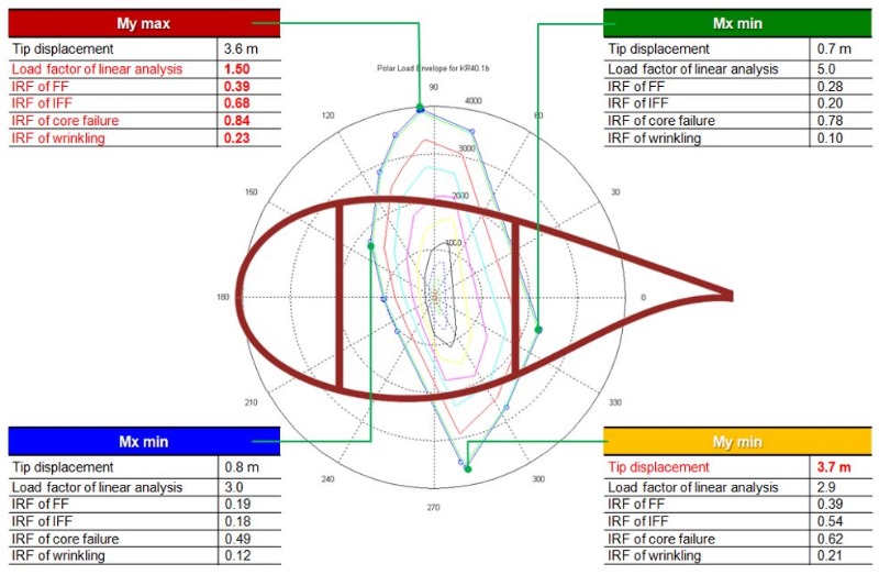
[Summary of design evaluation results]
5. Conclusion
The design of the final blade structure was completed through several iterative structural designs, and the structural analysis results were analyzed during the structural design process and optimization of the span cap and foam thickness was made by comparing with commercial blade characteristic values. In addition, the maximum deformation of the blade and the clearance with the tower were verified. The various evaluations such as laminate failure evaluation, buckling stability evaluation, sandwich structure evaluation, bolt connection evaluation and fatigue life evaluation were carried out all taking into consideration the characteristics of the composite blade.
Through this study, we have developed a blade model unique to the Korean Register of Shipping. We expect to use the technology acquired in this study for additional research and the development and evaluation of further blade design technology.

[Wind turbine Blade of KR 2MW]


