 KR Webzine Vol.110
- Dec. 2021
- Nov. 2021
- Oct. 2021
- Sep. 2021
- Aug. 2021
- Jul. 2021
- Jun. 2021
- May. 2021
- Apr. 2021
- Mar. 2021
- Feb. 2021
- Jan. 2021
- Dec. 2020
- Nov. 2020
- Oct. 2020
- Sep. 2020
- Aug. 2020
- Jul. 2020
- Jun. 2020
- May. 2020
- Apr. 2020
- Mar. 2020
- Feb. 2020
- Jan. 2020
- Dec. 2019
- Nov. 2019
- Oct. 2019
- Sep. 2019
- Aug. 2019
- Jul. 2019
- Jun. 2019
- May. 2019
- Apr. 2019
- Mar. 2019
- Feb. 2019
- Jan. 2019
- Dec. 2018
- Nov. 2018
- Oct. 2018
- Sep. 2018
- Aug. 2018
- Jul. 2018
- Jun. 2018
- May. 2018
- Apr. 2018
- Mar. 2018
- Feb. 2018
- Jan. 2018
- Dec. 2017
- Nov. 2017
- Oct. 2017
- Sep. 2017
- Aug. 2017
- Jul. 2017
- Jun. 2017
- May. 2017
- Apr. 2017
- Mar. 2017
- Feb. 2017
- Jan. 2017
- Dec. 2016
- Nov. 2016
- Oct. 2016
- Sep. 2016
- Aug. 2016
- Jul. 2016
- Jun. 2016
- May. 2016
- Apr. 2016
- Mar. 2016
- Feb. 2016
- Jan. 2016
- Dec. 2015
- Nov. 2015
- Oct. 2015
- Sep. 2015
- Aug. 2015
- Jul. 2015
- Jun. 2015
- May. 2015
- Apr. 2015
- Mar. 2015
- Feb. 2015
- Jan. 2015
- Dec. 2014
- Nov. 2014
- Oct. 2014
- Sep. 2014
- Aug. 2014
- Jul. 2014
- Jun. 2014
- May. 2014
- Apr. 2014
- Mar. 2014
- Feb. 2014
- Jan. 2014
- Dec. 2013
- Nov. 2013
- Oct. 2013
- Sep. 2013
- Aug. 2013
- Jul. 2013
- Jun. 2013
- May. 2013
- Apr. 2013
- Mar. 2013
- Jan. 2013
- Dec. 2012
- Nov. 2012
- Oct. 2012
- Sep. 2012
- Aug. 2012
- Jul. 2012
- Jun. 2012
- May. 2012
- Apr. 2012
- Mar. 2012
- Feb. 2012
- Jan. 2012
- Dec. 2011
- Nov. 2011
- Oct. 2011
- Sep. 2011
- Aug. 2011
- Jul. 2011
- Jun. 2011
- May. 2011
- Apr. 2011
- Mar. 2011
- Feb. 2011
- Jan. 2011
- Dec. 2010
- Nov. 2010
- Oct. 2010
- Sep. 2010
- Aug. 2010
- Jul. 2010
- Jun. 2010
- May. 2010
- Apr. 2010
- Mar. 2010
- Feb. 2010
- Jan. 2010
- Dec. 2009
- Nov. 2009
- Oct. 2009
- Sep. 2009
- Aug. 2009
- Jul. 2009
- Jun. 2009
- May. 2009
- Apr. 2009
- Mar. 2009
- Feb. 2009
- Jan. 2009
- Dec. 2008
- Nov. 2008
- Oct. 2008
- Sep. 2008
- Aug. 2008
- Jul. 2008
- Jun. 2008
- May. 2008
- Apr. 2008
- Mar. 2008
- Feb. 2008
04
April 2017
- KR Inside
- KR R&D Trends
-
Technical News
- Implementation of BWM Convention
- Dirty Vessel ordered to leave New Zealand
- Oil filtering equipment and control of operational discharge of Oil
- Notice of amendments to the KR Technical Rules (Rules for Part 10 and Guidance for Part 4)
- PSC Information (Marine Safety Alert - 1616 / 1617 released by USCG)
- Port State Control detentions
1. Introduction
In recent years, wind energy has become one of the most important and affordable
renewable energy sources. This has been demonstrated by the fact that installed
capacity has increased by around 30% annually and has increased by 10 times, wind powers’ share of the world’s electricity generation since 1996. Over the same period, the size of the average turbine has increased significantly. The blades of a wind turbine are key and are complex structural components to design.
The orthotropic material properties, the non-uniform distribution of different materials and the unique shape of the blade all contribute to the complexity of the wind blade.
To model this complexity, usually FE models are employed which help to explore the
distribution of strains and stresses within the blade.
For the structural design of the blade, a load analysis of the multi-body wind turbine system using the industry standard Blade Element Momentum(BEM) codes must be performed.
The BEM codes require blade information such as stiffness and mass distribution of the blade. In this regard, an aerodynamic and structural blade model normally represents the blade as a series of 1-dimensional (1D) beam elements in Fig.1, and the 1D elements must accurately represent all of the mechanical properties of the full 3D blade with coupling between the various forces. However, to capture all of this information by examining the sections alone has led to approximations and the omission of important aspects.
In the present study, the improved procedure of equivalent beam modeling is proposed based on the 3D model, and in order to compare the accuracy of the numerical results, the total weight calculation and modal analysis are performed.
2. Method
In this paper, a 2MW(Mega Watt) blade model is adopted and its transforming procedure from a 3D to a 1D model is introduced with the improved equivalent beam modeling process using blade element concept. The 3D blade is divided into 33 blade sectional elements along the length direction to obtain characteristic data such as mass, moments of inertia and stiffness of each divided blade elements.
The blade elements are assigned a number from 1 to 33, respectively, and then their individual properties computed. Each blade element is connected with MPC (Multi Purpose Coupleling) 184 at right and left side in Fig.2 which is employed for the boundary conditions and load conditions, respectively for the necessary computation purposes. The central nodal points are connected to the outer part of the blade section using MPC 184 element, which serves the role of evenly dividing the load and boundary condition applied to the section. The degree of freedom is restricted by assigning
boundary condition (fixed) in the left center, and a unit load is assigned to each direction (flap & edge wise, torsion) in the right nodal point. The unit load (ex, 1 KNm) is assigned to nodal point of each section as for each direction and the displacement and rotation angle in each case is computed. The unit load (), displacement () and rotation angle () are calculated with FEA results and then sectional stiffness for each blade element () is computed with the Eq. 1 ~ 3.
Edge wise stiffness: 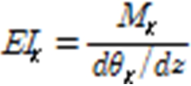 (1)
(1)

Edge wise stiffness: 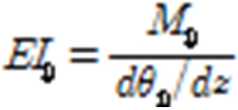 (2)
(2)

Edge wise stiffness: 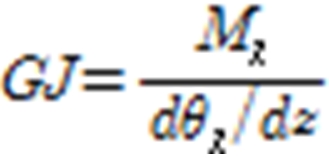 (3)
(3)

3. Result
To verify that the computation was executed according to an accurate procedure, a comparison of the structural characteristics of the original blade model and equivalent beam model was conducted.
A mutual comparison of the structural characteristics was conducted by comparing the entire weight, mode shape and natural frequency.
In the case of total blade weight, the 3D model was 7397.6 kg, and the value computed by the equivalent beam model as 7397.58 kg, which was almost exactly the same. This does not mean that both models have the same mass distribution, even though the totalmass between 1D and 3D model is the same. To clarify, the natural frequency and mode shape comparison are needed. Using the obtained stiffness and mass properties, the free vibration analysis is carried out and natural frequencies are acquired.
In Table 1, the structural analysis results of the 1D and 3D are presented. In terms of natural frequencies, the 1D model demonstrates a satisfactory correlation with the 3D model illustrated by the relative difference in terms of the natural frequencies. In fact, natural frequencies are usually determined only for the lowest 3-4 flexural bending modes and for the first torsional mode. The 1st ~ 4th degree natural frequency and mode shape matched each other within a 2.6 % error margin. Especially, even in the 7th degree mode where torsion mode occurs, the natural frequency and mode shape of the two models match well.
The comparison between 1D beam model results from ANSYS and GH Bladed, and 3D model from ANSYS are also quietly coincided in Fig 3, so the equivalent beam modeling of the 3D model is evaluated to have been accurately conducted.
Table1. Natural frequency comparison between 3D and 1D model
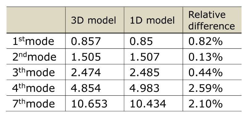
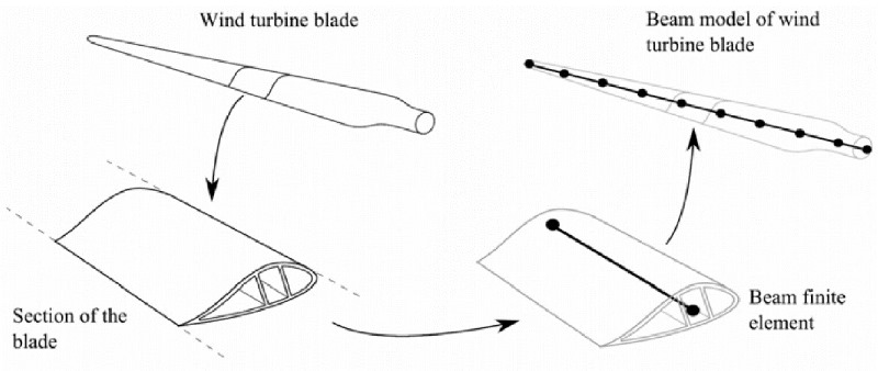
Fig1. Schematic diagram for blade element models
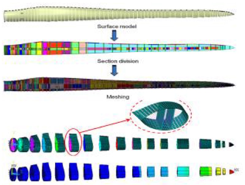
Fig2. FE model and section divisions of blade with MPC184 coupling
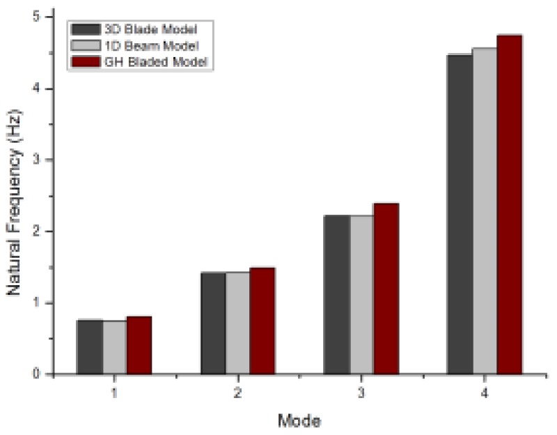
Fig3. Comparison of natural frequency results between 3D, 1D and GH Bladed model
4. Conclusion
This paper provides an improved approach that enables the extraction of the structural properties of a composite wind turbine blade, while showing a good accuracy of its structural characteristics compared to its 3D FE blade model. The FE model used a 2MW wind turbine blade and an equivalent beam model as a load calculation tool (ex, GH
Bladed, Flex5) is developed.
This methodology is based on a numerical model of the composite blade with a blade element concept, each blade element is connected with MPC 184 and then boundary conditions and load conditions were assigned respectively. The degree of freedom was restricted by assigning a boundary condition (fixed) in the left center, and the unit load was assigned to each direction (flap & edge wise, torsion) in the right nodal point.
After the unit load, the results of the displacement and rotation angle in each case were computed. Similarly, the sectional mass and inertia moment for Z directional also are calculated. For validation of its compatibility, a comparison between a 3D model and 1D beam model is processed with the total mass, natural frequencies and mode shape.
Despite the simplicity of the approach, the excellent agreement observed in the model validation is attributed to the predictive capability of this procedure.
References
Bechly ME, "Structural design of a composite wind turbine blade using finite element
analysis," Computers & Structures, 1997.
Lanzafame R, Messina, "Fluid dynamics wind turbine design: Critical analysis, optimization and application of BEM theory," Renewable Energy vol. 32, pp. 2291-2305, 2007.
Bir GS, Migliore PG, "Computerized method for preliminary structural design of composite wind turbine blades". Journal of solar energy engineering, vol. 123, iss. 4, pp. 372-381, 2001.


